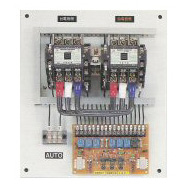
Automatic Transfer Switch (ATS)
A.T.S. is an important component of the overall system and the design must match the
basic requirements.
 |
 |
- Automatic Transfer Switch (ATS) is a device used to automatically switch a power supply from normal (utility) to emergency (generator) when a power failure occurs.
- When the normal (utility) power is restored the load is transferred back to normal source.
- Automatic Transfer Switch can make use of two or more power supplies in a system ensuring power supply to critical and non-critical loads depending upon the type of the A.T.S. and its configuration.
Standard ATS Functions
Time Delay on Engine Starting (TDES)
TDES provides a time delay of the signal to initiate the engine/generator start cycle in order to override momentary power outages or voltage fluctuations of the Normal Source. Adjustable 0 – 30 seconds.
Time Delay Normal to Emergency (TDNE)
Provides a time delay when transferring from the Normal Source to the Emergency Source. Timing begins when the Emergency Source becomes available. Permits controlled transfer of the load circuit to the Emergency Source. Adjustable 0 – 1800 seconds.
Time Delay Emergency to Normal (TDEN)
Provides a time delay of the re-transfer operation to permit stabilization of the Normal Source. Timing begins when the Normal Source becomes available. If the Emergency Source fails during timing, then re-transfer is immediate overriding the time delay. Adjustable 0 – 60 seconds.
Time Delay for Engine Cool-Off (TDEC)
Provides a time delay of the signal to initiate the engine/generator stop cycle after the re-transfer operation. This allows the engine/generator to cooldown by running unloaded. Timing begins on completion of the re-transfer cycle. Adjustable 0 – 30 seconds.
Test Switch
This Test Pushbutton that simulates a loss of the Normal Power Source. All programmed time delays (TDNE, TDEN, etc.) will be performed as part of the Test. Engine run time of the Test is equal to the Plant Exerciser programmed set point.
By-Pass Push Button
Provides a momentary contact pushbutton to bypass the TDNE (Function 2) and/or TDEN (Function 3) time delays. The Time Delay Bypass Pushbutton contact, when closed, will reduce any or all of the programmed time delay to zero.
Pilot Lights
Provides pilot lights to give power source(s) availability indication.
a) Normal Power Source Load Indicator Light (Green)
b) Emergency Power Source Load Indicator Light (Red)
Engine Start Contacts
To control engine startup.
Auxiliary Relay Contact
Auxiliary relay contact for Normal Power Supply or for Emergency Power Supply.
Bar
The bar can be used to transfer load from Normal Power Supply to Emergency Power Supply and vice-versa.
Battery Charger
Provides an automatic battery charger with 12V and 24V DC output.
Control Fuse
Fuse for the control circuit. Installed at the main controlling circuit.
Control Circuit Breaker
This type of low current No-Fuse Breaker (NFB) is installed for the protection of control circuit and for the replacement and service of parts and components.
a) Normal Power Supply: 10A,3P b) Emergency Power Supply: 10A,3PBUS
Provision for bus bar connection.
Plant Exerciser
Provides a means for automatic testing of the engine generator set or standby power system. All programmed time delays will be performed during plant exerciser operations. This includes a user programmable set point for test intervals. Test may be performed with or without load circuit transfer. Test may be manually cancelled during operation. Adjustable engine run time 0 – 168 minutes. It can be run at least once a week for 15 minutes.
Under Voltage Protection
Contains standard protection on all phases for normal power source. Installing 'Under Voltage Relay' (adjustable to 70%-90% of voltage drop) can recover voltage by 90%.
Over Voltage Protection
Installing 'Over Voltage Relay', adjustable to 105% of voltage surge and surge protection at 115%.
Instrument Panel on External Box
- Voltage meter
- Current meter
- Frequency meter
- Charging current meter
Standard Components
- Main switch [No-Fuse Breaker (NFB), MC, Molded Case Circuit-Breaker (MCCB), Air Circuit-Breaker (ACB)]
- Mechanical Interlock
- Electrical Interlock
- Printed Circuit Board (P.C.B.) for Control Panel
- Remote engine start-up connection
ATS Models
| Model | Rated limit short circuit breaking capability (KA) | Frame Current (AF) | Rated Current (AT) | Rated Working Voltage | Poles |
| 440V/KA | A | A | A | ||
| CL-3P50M | 50 | 30,40,50,60 | 440 | 3 | |
| CL-3P100B | 15 | 100 | 15,20,30,40,50,60,75,100 | 440 | 3 |
| CL-3P100G | 15 | 100 | 15,20,30,40,50,60,75,100 | 440 | 3 |
| CL-3P100M | 100 | 100 | 440 | 3 | |
| CL-4P100G | 15 | 100 | 15,20,30,40,50,60,75,100 | 440 | 4 |
| CL-3P225B | 15 | 225 | 125,150,175,200,225 | 440 | 3 |
| CL-3P225G | 15 | 225 | 125,150,175,200,225 | 440 | 3 |
| CL-4P225G | 15 | 225 | 125,150,175,200,225 | 440 | 4 |
| CL-3P400G | 25 | 400 | 250,300,350,400 | 440 | 3 |
| CL-4P400G | 25 | 400 | 250,300,400 | 440 | 4 |
| CL-3P600G | 25 | 600 | 500,600 | 440 | 3 |
| CL-4P600G | 25 | 600 | 500,600 | 440 | 4 |
| CL-3P800G | 25 | 800 | 700,800 | 440 | 3 |
| CL-4P800G | 25 | 800 | 700,800 | 440 | 4 |
| CL-3P1200G | 50 | 1200 | 10,001,200 | 440 | 3 |
| CL-4P1200G | 50 | 1200 | 10,001,200 | 440 | 4 |
| CL-3P1600G | 50 | 1600 | 14,001,600 | 440 | 3 |
| CL-3P2000NE | 65 | 2000 | 1600 | 440 | 3 |
| CL-4P2000NE | 65 | 2000 | 2000 | 440 | 4 |
| CL-3P3000NE | 85 | 3000 | 3000 | 440 | 3 |
| CL-4P3000NE | 85 | 3000 | 3000 | 440 | 4 |
| CL-3P4000NE | 85 | 4000 | 4000 | 440 | 3 |
| CL-4P4000NE | 85 | 4000 | 4000 | 440 | 4 |
| CL-3P5000NE | 100 | 5000 | 5000 | 440 | 3 |
| CL-4P5000NE | 100 | 5000 | 5000 | 440 | 4 |
Our Products Gallery
Contact Chao Li
Chao Li Electrical Group
Tel: (886)-4-23354488
Fax:(886)-4-23354334
Address: No. 188,, Thai-Ming Road, Wu Ri
District, Taichung Country, Taichung, Taiwan